Designing my own keyboard from scratch - Part 2: The Schematic

Before you can create the PCB, you need a schematic. The schematic is a diagram that shows how electric components come together to form a complete circuit; it's an electronics blueprint. You've seen schematics before in your school career:
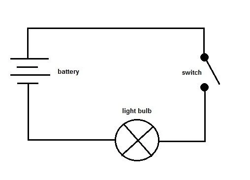
Schematics use standardized symbols so that they can be easily shared, interpreted, and developed. We'll create a schematic first so that we can not only plan our PCB, but also as we'll need it to create the physical PCB design that can then be manufactured.
The Software
We'll create both the schematic and the PCB itself using KiCad, which is a free piece of software that's available on multiple platforms and powerful with what it can create.
KiCad can be used to create any PCBs and schematics, not just for keyboards. With that said, it's very widely used in the keyboard community, likely due to its free nature and, in my opinion, intuitive interface. It's also packed with a suite of useful tools like calculators and editors, the ability to install plugins, customise the interface, and lots of other things.
I spoke last time about this video from ScottoKeebs, which is a great intro to keyboard design and how I got started. It covers how to create any keyboard you want, even non-standard ones, from schematic to PCB to production. However, it doesn't cover PCB design fundamentals. This video from iNimbleSloth is longer but goes into more detail, specifically on keyboards and a few key things to consider in PCB design. I started with these two videos, though there are plenty of good guides.
Before you even jump into designing schematics and keyboards, you first need to understand how keyboards work on an electrical level - that's where the Keyboard Matrix comes in.
The Keyboard Matrix
Before you watch any design video, this short video from ScottoKeebs gives an overview of how keyboards work and how you can wire them. Ultimately, there are two main approaches - Matrix or direct wire.
For a bit of context, all keyboards have a microcontroller that stores the keyboard's firmware and uses that firmware to interpret physical keypresses (switches closing a circuit) into a signal that's interpreted as a keystroke on your computer. All microcontrollers will have input/output (I/O) pins that can process incoming signals and send them out. Why does this matter?
Well, keyboards have tens of switches and full-size keyboards have over 100 switches. You can hook up each switch to an individual I/O pin on the controller (direct wire) so it knows that any signals going to that pin is that switch and that switch only, but there's a problem. Most microcontrollers don't have that many I/O pins (often referred to as GPIO pins, or General Purpose Input Output), so you will run out of GPIO pins before you can hook up every switch; it's just not feasible or practical to give each switch its own GPIO pin.
So, how do you get around having more switches than GPIO pins? You use what's known as a keyboard matrix. Rather than giving each switch its own GPIO pin, you group all switches into an array of rows and columns and then assign each row and each column its own GPIO pin. In a keyboard that has, say, 5 rows and 10 columns, you only need 15 GPIO pins (5 for each row + 10 for each column) in total - perfect for when most microcontrollers have 30 or so GPIO pins at most, though you can get microcontrollers that have more.
So how do they work? It's very similar to a coordinate system. Let's say you want to press the letter 'Q' on your keyboard. The switch for the letter 'Q' could sit on, say, Row 2 and Column 2. When you press the 'Q' keyswitch, it closes the circuit and lights up Row 2 and Column 2. When the microcontroller sees that both Row 2 and Column 2 are lit up, it knows that 'Q' has been pressed.
The Microcontroller
The microcontroller (MCU) is the hardware that's the heart of your keyboard - everything flows in and out of it. All components on a keyboard connect to the MCU, and the MCU sits in between the individual components and the computer itself. The MCU is a neat little package that has multiple smaller components rolled into one. It has flash memory (which stores data), a processing core or two, a RAM buffer, an internal clock, connectivity components, and sometimes built-in voltage regulators.
Microcontrollers are used in anything that needs data to be processed - keyboards, mice, card readers, microwaves - anything you can think of that has remotely any sort of logic or inputs and outputs. In the context of a keyboard, it's what will tie everything together and store the firmware. They're often small in size, both the physical package and their processing power. They do really basic stuff, so they don't need to be big or powerful like CPUs in a computer.
When you're designing a keyboard, you'll need to pick an MCU that suits your needs. What firmware do you want to run? How many GPIO pins do you need? How much flash memory do you need? How big does it need to be? As a rule of thumb, I recommend an MCU that has 30 GPIO pins or more and at least 32kB of flash memory to store the firmware. 30 GPIO pins give you enough I/O for the number of rows and columns needed to create a full-size keyboard, while >32kB of flash memory gives you enough space to load firmware that gives you full functionality.
It's technically possible to do keyboards with fewer GPIO pins and less flash memory, but it becomes far more difficult and means you have to strip back a lot of features to make it work. In all honesty, there are plenty of MCUs that meet these requirements or more, so there's no reason not to pick something less than this. A decent indicator of picking a Microcontroller is this page of supported Microcontrollers that can be used for QMK firmware, which is the gold standard of creating your keyboard firmware (though more on this in Part 5).
The two most common Microcontrollers that people use to develop keyboards are the RP2040 made by the Raspberry Pi foundation, and the Atmel ATmega32U4. Both are fully supported when developing QMK firmware and have enough pins and flash memory. Microcontrollers can either be bought on their own as just the microchip or as part of a package that has not only the microchip but other built-in components like a USB port, voltage regulator, boot buttons, etc. An example of this is the Raspberry Pi Pico, which is very commonly used for building keyboards and contains not only the RP2040 MCU but also a USB port, easily accessible GPIO pins, a boot selection button, and so on.


An Atmel ATmega32U4 (left), a microcontroller, and a Raspberry Pi Pico (right), a package using the RP2040 MCU
You'll want to do some research on what your needs are, which will help you narrow down your Microcontroller, as well as whether to get the chip by itself or as part of a package. There are pros and cons for each:
MCU only
- Pro - Physically smaller in size, takes up less space and is easier to mount
- Pro - Doesn't contain unnecessary components you may not need
- Pro - Wider range of choice, not all MCUs are packaged
- Con - Difficult to solder, as you're often dealing with small pins
- Con - Might be difficult to source by themselves, may sometimes have a minimum buy quantity
MCU package
- Pro - Everything is bundled into one convenient package, and no additional components or design are needed
- Pro - Easier to solder onto the main PCB
- Pro - Widely available
- Con - Bulkier, takes up more space
- Con - A bit more expensive than just the MCU by itself
While not an exhaustive list, this will give you a general idea. For a first-time build, I'd recommend going for a full package, like a Pi Pico. It'll be easy to mount, load the firmware, and most importantly, it already has a USB-C connector - you won't have to develop your own connector onto the PCB.
The Full Schematic
Once you know what layout you want to use and what microcontroller you'll use, you should start to plot out your keyboard and its matrix. There are two excellent pages you can use in tandem with each other to develop your keyboard:
Keyboard Layout Editor allows you to map out the physical layout of your keyboard. You can use one of multiple presets for common layouts or create a layout from scratch. The page is very versatile and can define exact key locations, sizes, mounting types, etc. Most importantly, you can save your keyboard layout as a JSON file, which stores the configuration of your layout.
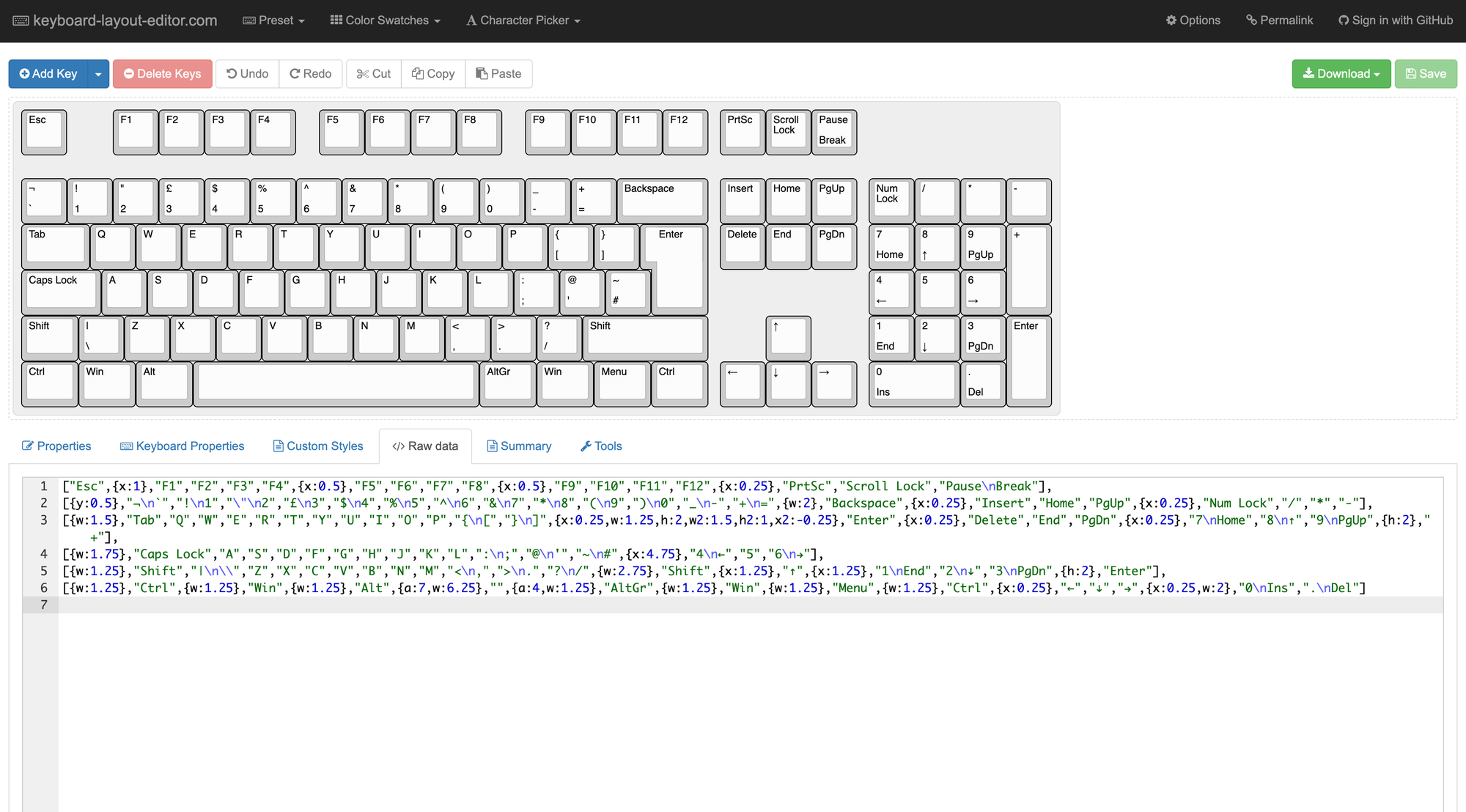
It's not only helpful to keep a record of your layout, but we'll also use it to import your keyboard into Keyboard PCB Builder, which will auto-generate your matrix for you.
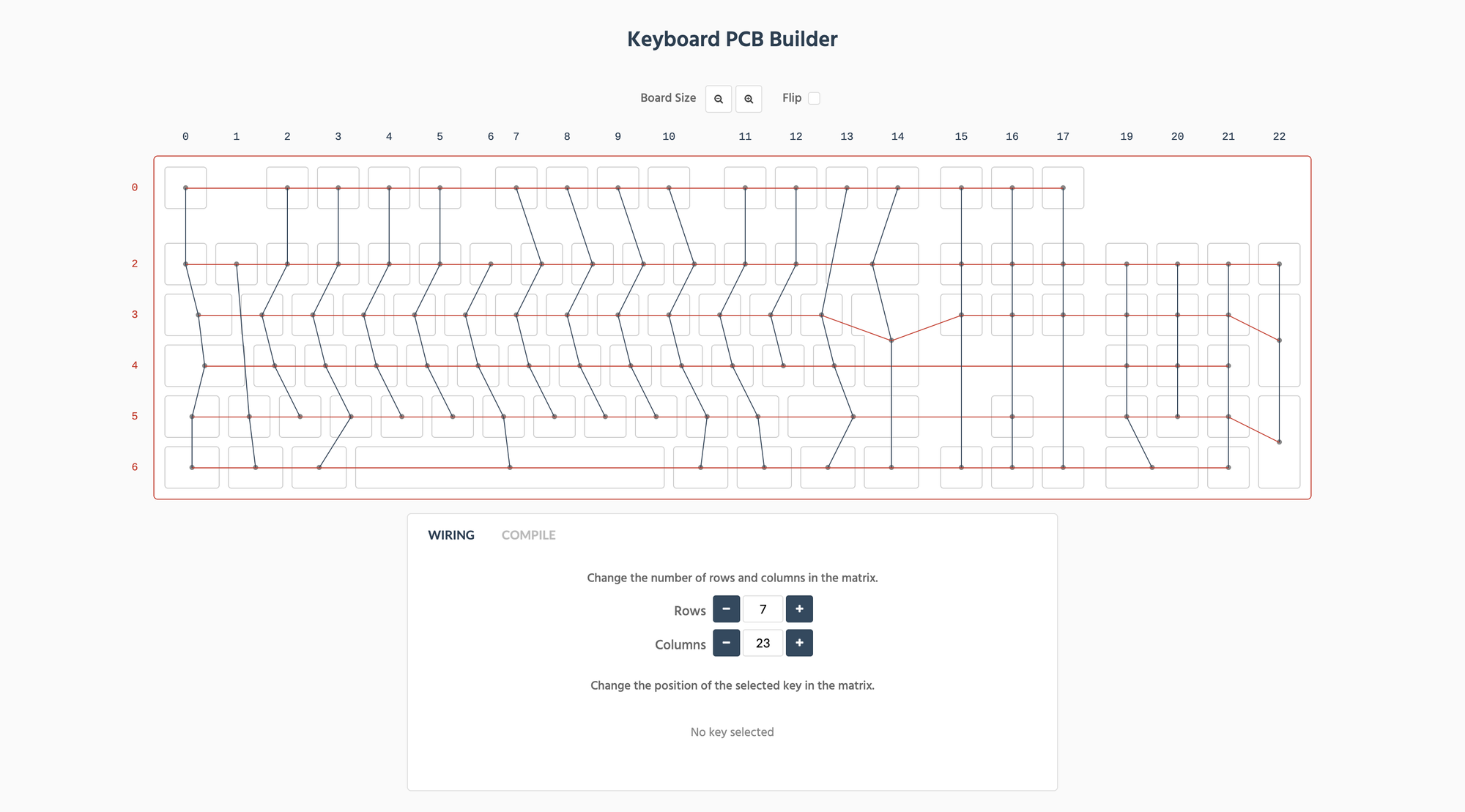
But those aren't all the tricks that Keyboard PCB Builder has up its sleeve. It will also generate a KiCad schematic file with the exact layout and matrix that you need, saving you the hard work and allowing you to go straight to creating the PCB. Personally, I still create the schematic from scratch as the auto-generated file makes it annoying to add any custom components or make any changes.
With all of this in mind, we can start to develop the schematic itself. Assuming you have KiCad (or your software of choice) set up and have the schematic editor open, begin to build your array of switches. If you're using KiCad, I highly recommend adding ScottoKeebs' symbols and footprints (follow the guide in his video above), as this contains a lot of common parts used in keyboards that will make developing the PCB a breeze.
For your initial keyswitch, add a switch and connect a diode to it as well:
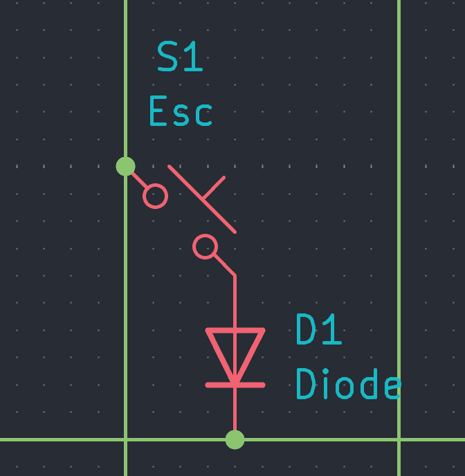
While the diode isn't strictly necessary, it's highly recommended to add to keyboard matrices and features in pretty much all keyboards. A diode allows current to flow only in one direction, meaning a signal can't go back on itself or come from an unintended direction. The reason why it's added to each switch when developing keyboard matrices is because it prevents an issue called key ghosting. Key ghosting is when you press a key, but the input from pressing that key doesn't register. This can happen if you're pressing multiple keys at once (e.g. pressing key combinations like Ctrl + C and Ctrl + V or playing video games).
For example, you might want to press the 'G' key - that's a key that's in the middle of the keyboard and sits amongst multiple different columns and rows in a matrix. If you were to press the 'G' key in a matrix without diodes, that could flow back up the column or row it's sitting in and/or prevent you from pressing any other keys at the same time because the electrical signal lights up the entire column and/or row the 'G' key is in, so other keys in that same column or row can't be pressed.
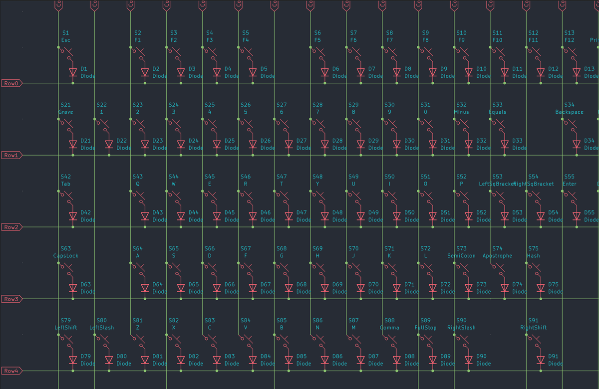
Once you have the initial keyswitch + diode, you can copy-paste it multiple times to build your rows of switches. Once you have all of your switches lined up, begin to connect them. If you're using KiCad, you can use Global Labels to tie up each switch into rows and columns:
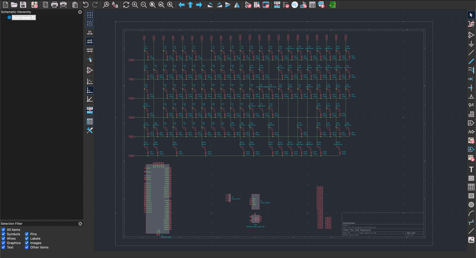
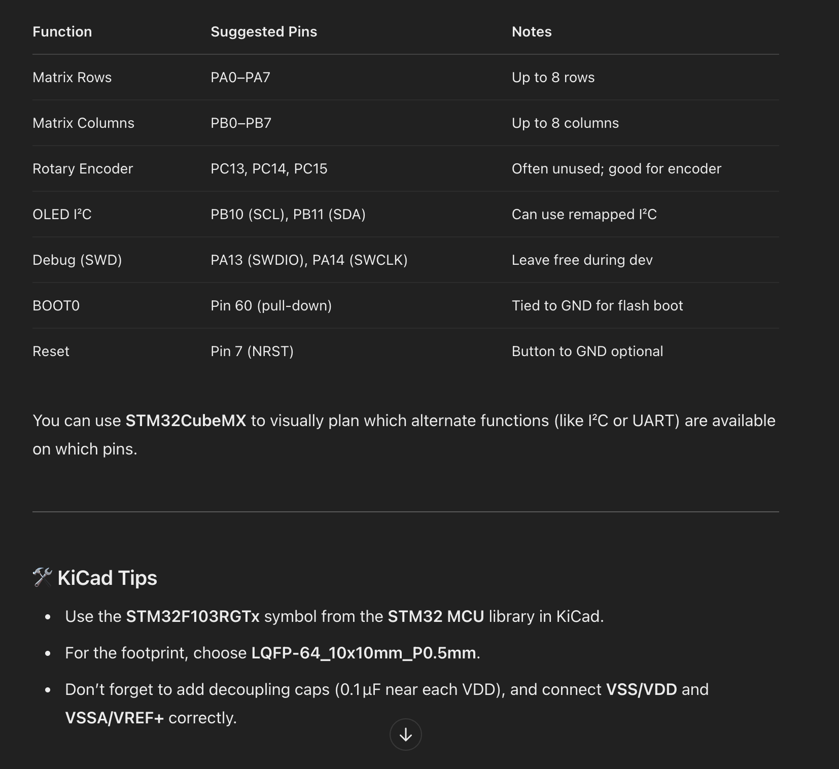
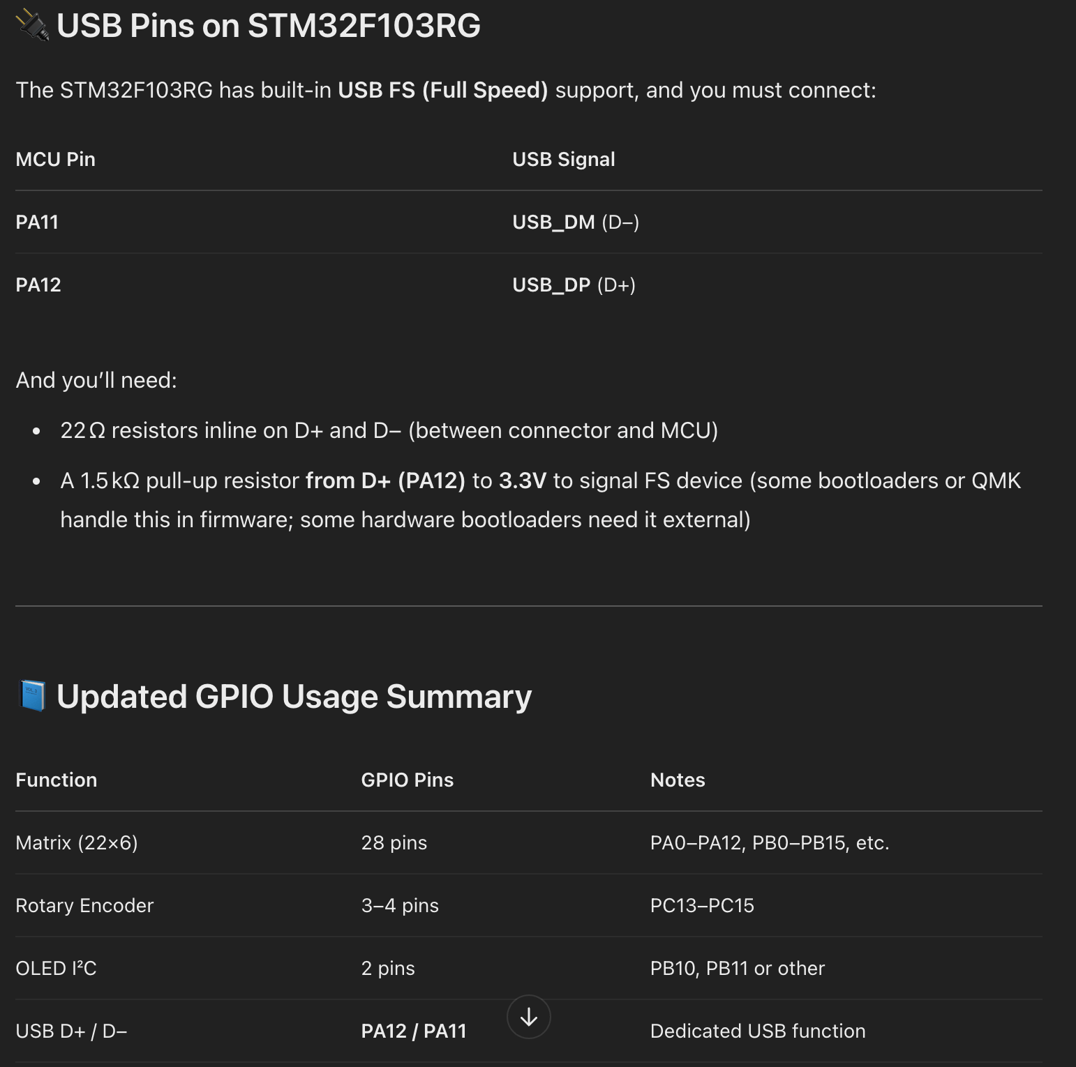
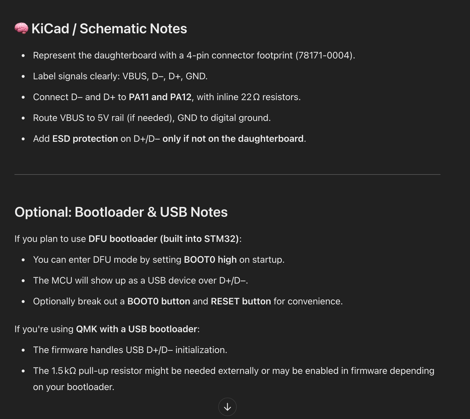
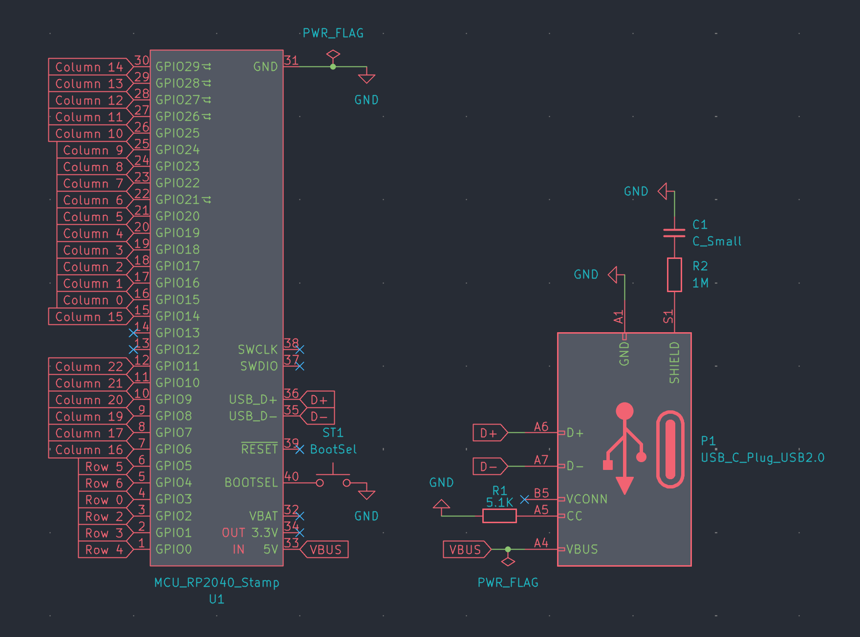
We can then use the global labels to start connecting them cleanly and easily to the GPIO pins on the microcontroller of your choice. I've also added a few representations of the microcontroller I'll be using, as well as the rotary encoder, OLED display, and connector that will be used for the daughterboard. The next step will be connecting the labels and everything else together.
At this stage, you do not need every single component to be physically located where it will live on the keyboard - this is only a representation; we'll align everything in the PCB Editor later. The important thing is that everything is connected properly.
At this stage, you may be where I am and be thinking, "How do I know what to connect to which pin? Help!" It's a very fair question to ask - this is one of the harder parts of PCB design. The main things to assign at the moment are the different components (if you have them) to the microcontroller's GPIO pins. While you will need to assign the column and row global labels for the time being, their placement is final, so don't worry about them - we'll revisit them when we design the PCB and route traces.
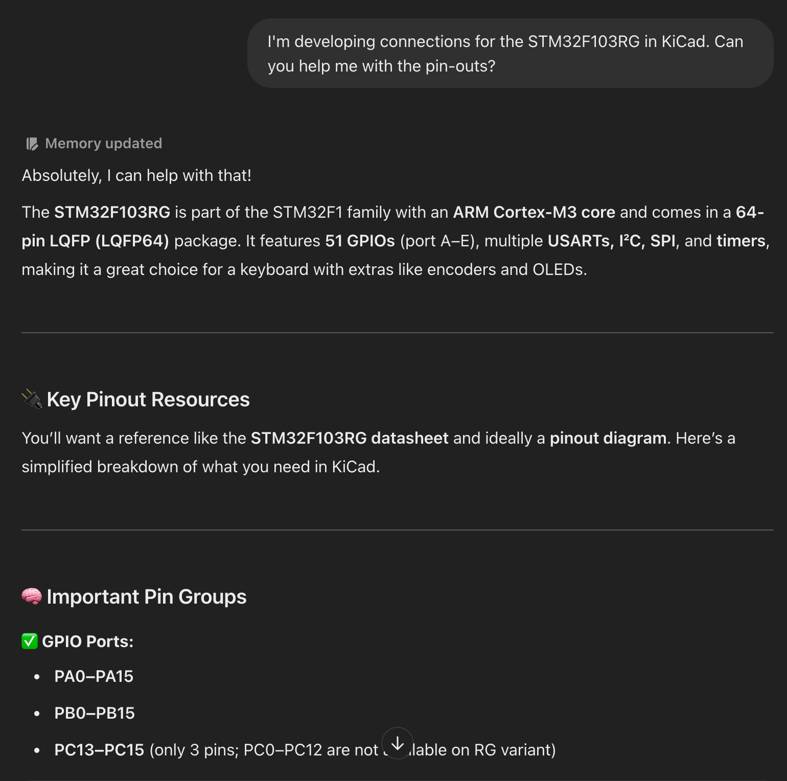
Let's take our OLED display as an example - how do we know which pins on the microcontroller it needs to be assigned to? You can't just randomly connect them and hope for them to work because some or all of the pins on the OLED display need to be assigned to specific pins on the microcontroller. To know for sure, you'll want to consult the datasheets for both the microcontroller you're using and the components you're connecting.
Each electrical component you want to buy will have a datasheet created by the manufacturer - it contains detailed information on the specs of the part, what each pin means, what the requirements are, and so on. Some datasheets are clearer than others, while some can some very technical and hard to read. If you have lots of experience as a hobbyist or if you've previously worked with circuitry, then datasheets may be easier to interpret for you. However, if this is your first time and/or you have little to no experience with electronics, it can seem very daunting - almost as if you're reading a foreign language.
As an example, here's the Datasheet for the microcontroller I want to use, the STM32F103RG. This is a very typical, albeit technical and not as easy to read, datasheet. As a contrast, here's a Datasheet for the RP2040 Stamp which, in my opinion, is far easier to read and interpret - it's purely down to the manufacturer. The RP2040 Stamp is a hobbyist product, so its datasheet will be geared more towards being easy to understand for first-timers, while the ST datasheet is for a product that will probably be used in industrial applications by more experienced users, so an abundance of details is more important rather than simplifying things.
Once you understand what each pin does, you can start to figure out what pin needs to be connected to where. Datasheets alone aren't enough - you also need a basic knowledge of electricity and circuits. For example, you will need to route some pins to ground, some microcontrollers may need that the incoming 5 volts from USB needs to be reduced to 3.3V, so you need to know that you need to add a resistor, and how to calculate what value resistor you need (V=IR, R=V/I) and so on. Chances are if you're interested in building your own keyboard, then you already know (some of) this stuff already, but it's also perfectly likely that you don't, which is completely valid.
In cases where you don't know what to do or if you need to check something, you have a couple of options. You can either do your own independent research and learn electrical design theory, or you can just straight up ask ChatGPT - it is a godsend for this.
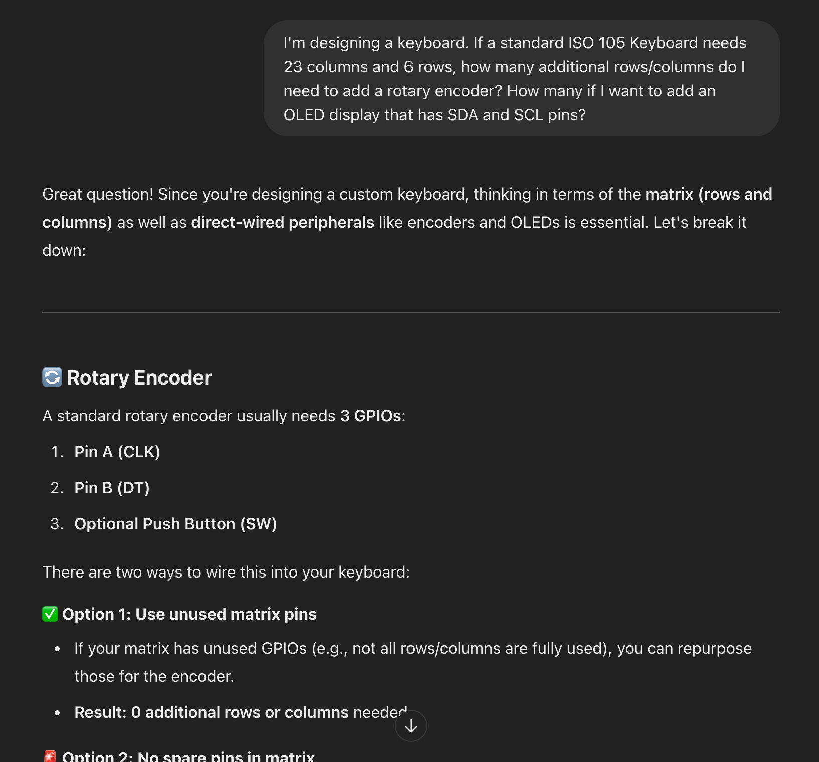


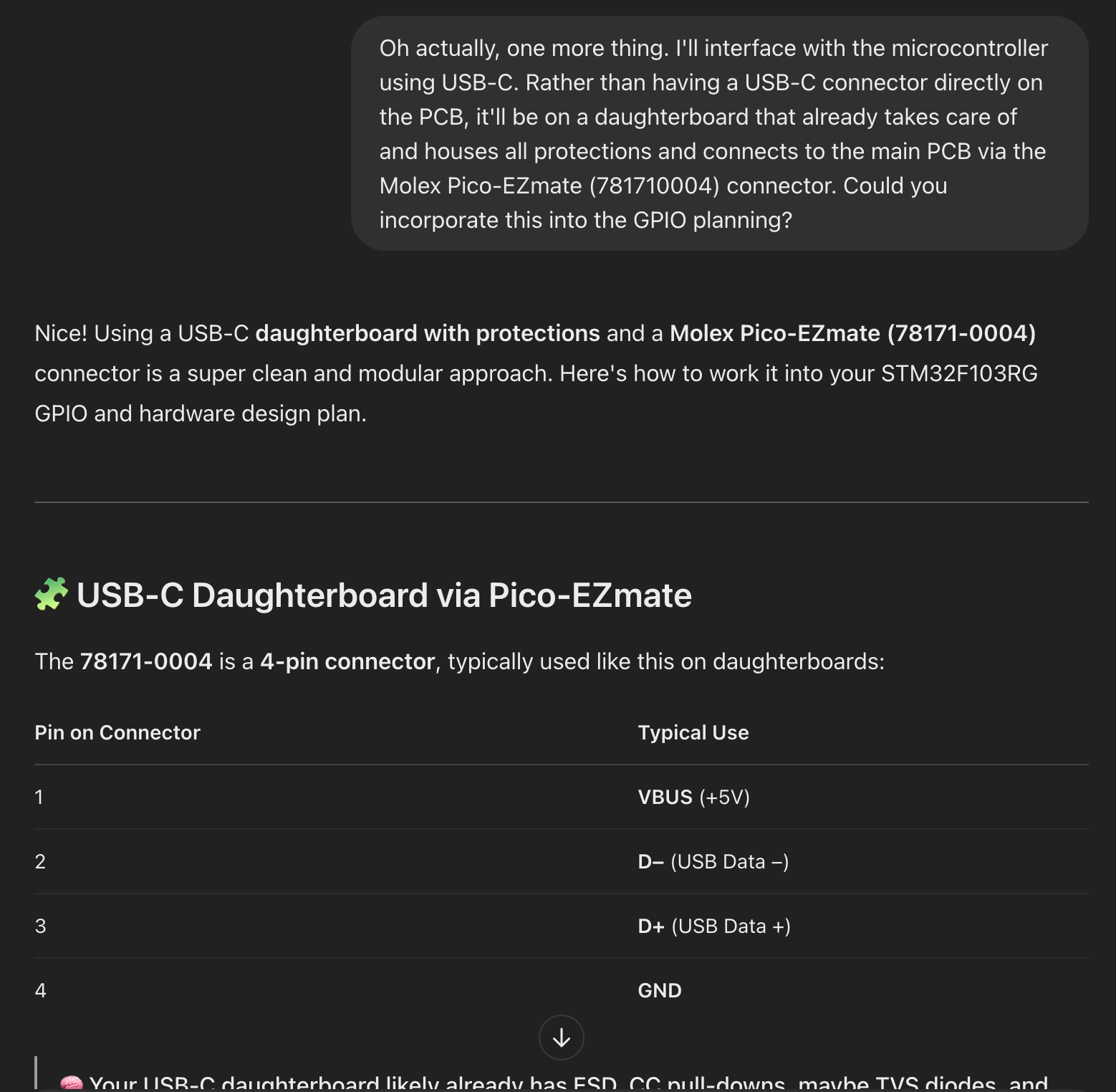
ChatGPT can help you plan stuff - all you need to know is how to ask questions
Seriously, I can't recommend ChatGPT enough - it still positively amazes me at how useful it is. I've mentioned using ChatGPT as an aid in previous posts, though I'll re-iterate my previous sentiment of how ChatGPT is like an infinitely knowledgable, patient friend that can answer any question you have. Before ChatGPT, we would've had to spend hours Googling stuff, trawling old forum posts, and spending several hours learning theory so you can understand for yourself (and even then without a guaranteed answer), but this just makes it so much easier.
I have used ChatGPT multiple times when I created v1.0 and v1.1 of my keyboard, and I continue to use it for v2.0.
Final preparation for creating a PCB
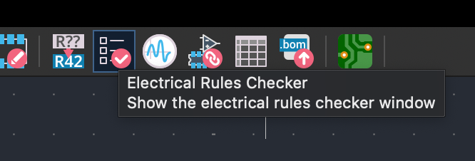
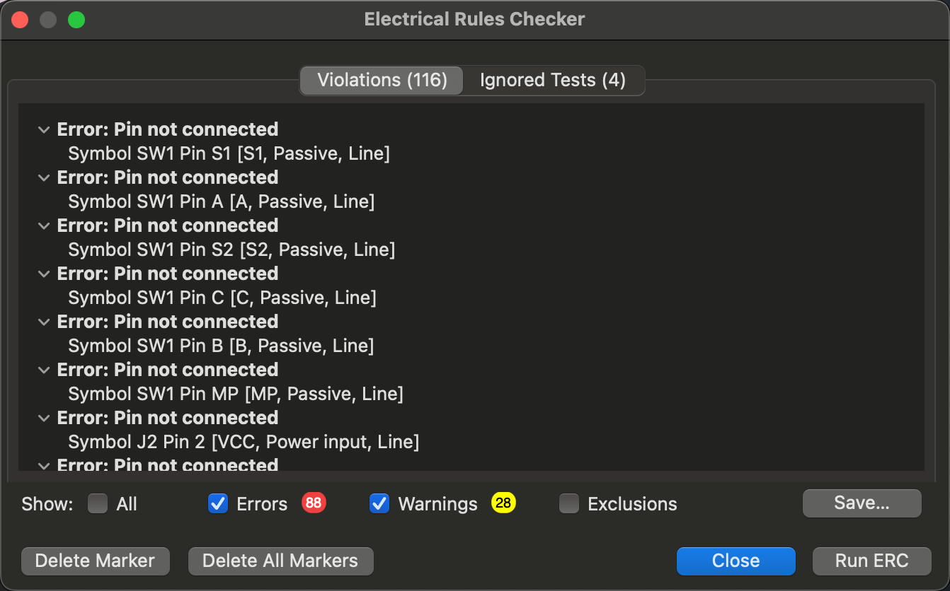
Once you've mapped all your pins and you're confident everything is hooked up correctly, you can check everything before starting to create a PCB. KiCad has a built-in feature named 'Electrical Rules Checker', abbreviated to ERC, that will check for any issues and tell you what you need to address. This makes sure that everything works and helps avoid any issues down the line.
Once open, run the ERC and check your work. You should have 0 errors and ideally 0 warnings as well, though a couple of warnings will be okay, depending on the nature of the warnings.
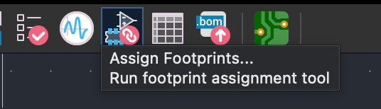
The last thing to do is to assign footprints in Kicad - this is defining exactly what components you'll use on the PCB once it's created. This part is extremely useful as it means you don't have to estimate what parts you'll use, what dimensions they'll occupy, or how to lay them out - they'll exist in the PCB editor as physical objects once you begin to design it.
This stage can feel quite overwhelming as you can have tens or even hundreds of individual components to choose from. For example, you might need a resistor - okay, what size resistor? What length, diameter, and thickness should it be? Do you want a surface-mounted (SMD) or through-hole (TMT) resistor? Picking from that many different possible components can be overwhelming and potentially infurating, potentially if you're thinking to yourself "I just want a simple resistor, why is this so complicated?".
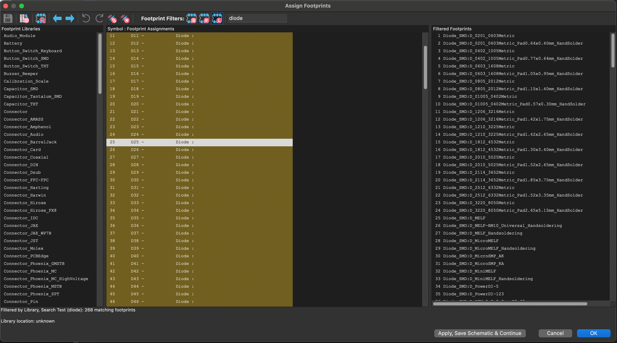
For common electric components like diodes, resistors, and USB connectors, my advice is to work backwards by first going to the retailer from which you intend to buy your components (Farnell, RS Components, Mouser, etc.), see what inventory they have, and then select that available inventory as your list of components in KiCad - this should help you narrow down the same component to use for your PCB that you'll actually be able to buy, if not a very similar alternative.
KiCad's default library of footprints and components is vast and covers pretty much everything you'll need. Equally, you always have the ability to expand KiCad's library by either adding bundles of footprints that others have created (Such as ScottoKeebs's footprints if you followed the video and downloaded his library from GitHub) or by creating your own custom footprints from scratch using one of KiCad's built-in tools.
Once you've assigned all your footprints and your ERC passes with flying colours, we'll be ready to start designing the physical PCB itself. At the moment, all we have is a schematic, a theoretical representation of the keyboard. While the keyboard works functionally, we actually need to lay out the components and bring it to life.